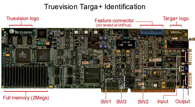
This page will help you identify the Targa+ and includes descriptions
of the switch settings and connector pin-outs.
You will need to know the settings of Switch 1 positions 1-3 so that
you can match to the selected Base I/O address in VPCONFIG.
Switch 1 (SW1):
Controls the I/O Base address and the I/O Mode.
  Defaults: UP, DOWN, UP, UP, UP.
  For VidPlus, switch positions 4 & 5 must remain UP.

  Switch positions 1-3 select the Base I/O address:
    I/O Base      1   2   3
    --------     --- --- ---
    0x200         U   U   U
    0x210         U   U   D
    0x220         U   D   U    (default)
    0x230         U   D   D    (recommended)
    0x240         D   U   U
    0x250         D   U   D
    0x260         D   D   U
    0x270         D   D   D
  I do not recommend using the 0x220 address because this
  is more recently the default address of many sound cards.
  Even if you have no sound card in your system, I recommend
  using 0x230.

  ----------------------------------------------
Switch 2 (SW2):
Controls output video selection.
  Default: DOWN = H/V Sync.
  This selects H/V Sync or S-Video out.  Due to the
  limited number of pins on the output connector, both
  H/V Sync and S-Video are not available simultaneously.

  Move the switch to the UP position if you are going
  to connect any S-Video equipment to the Targa+ output.

  Some boards have an SW2 switch that has (3) positions:
  UP, CENTER and DOWN.  Be sure the switch is either UP
  or DOWN, the CENTER position disables all output.

  ----------------------------------------------
Switch 3 (SW3):
Controls special interrupts to the Host computer.
  Defaults: DOWN, DOWN, DOWN, DOWN, DOWN = interrupts OFF.
  For VidPlus, all switch positions must remain DOWN.

  ----------------------------------------------
Video Connector Pin-Outs:
  INPUT:
    Pin #     Description
    -----     -----------
      1       Ground
      2       Ground
      3       Red
      4       Green
      5       Blue
      6       Composite Video
      7       Composite Sync
      8       Y (S-Video)
      9       C (S-Video)

  OUTPUT:
    Pin #     Description
    -----     -----------
      1       Ground
      2       Ground
      3       Red
      4       Green
      5       Blue
      6       Composite Video
      7       Composite Sync
      8       Y (S-Video)  or  H Sync (H/V Sync)
      9       C (S-Video)  or  V Sync (H/V Sync)